H & U Collars
H-Collar
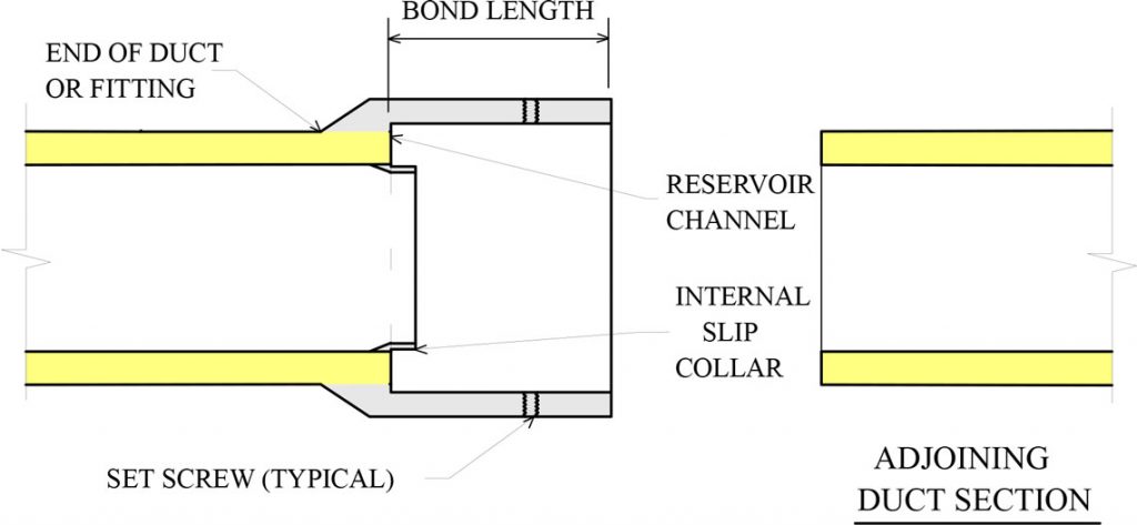
Installing ATS duct requires accurate measurement and cutting to insure a proper seal and bond when duct and fittings are connected using ATS H-Collars. The H-Collars consist of an internal slip collar, a reservoir channel, a structural area, set screws and an external structural collar. The adjoining duct and fitting ends must slide over the internal slip collar and into the reservoir channel to ensure a complete seal for ultimate corrosion resistance. See the “H” Collar Section below:
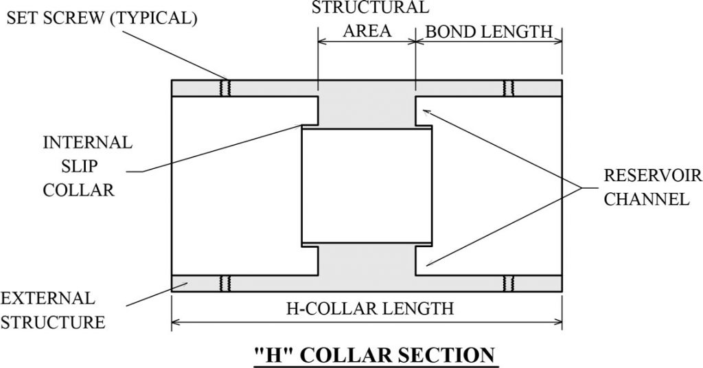
Therefore, when measuring duct to be cut for assembly, the Structural Area must be subtracted from the duct measurement to achieve the desired overall length of the assembly. The Structural Area is 1/2” for all H-Collars, so 1/2” must be subtracted from the duct or fitting to achieve the overall desired length.
Also, smooth radius elbows will fit properly into H-Collars, because of the extensions on the elbow ends. Large diameter elbows and special radius elbows are provided as Gored Elbows with extended legs equal to the Bond Length of the H-Collar. When figuring dimensions for fitting gored elbows into the duct assembly, use the following formula: For standard radius elbows the centerline to face is 1-1/2 times the diameter + Bond Length; for short radius elbows the centerline to face is the diameter + Bond Length. Example: A 10” diameter standard radius 90 elbow will have a centerline to face dimension of 16-3/4”.
| Part Type | Nominal diameter | Actual OD Inches | Nominal Dia. in mm | Bond Length/Side | Structural Area | Overall Length |
|---|---|---|---|---|---|---|
| 1002 | 2 | 2.25 | 50 | 3/4” | 1/2” | 2” |
| 1003 | 3 | 3.25 | 75 | 1” | 1/2” | 2 1/2” |
| 1004 | 4 | 4.25 | 100 | 1 3/4” | 1/2” | 4” |
| 1006 | 6 | 6.25 | 150 | 2 3/4” | 1/2” | 4” |
| 1008 | 8 | 8.25 | 200 | 3 3/4” | 1/2” | 4” |
| 1010 | 10 | 10.25 | 250 | 4 3/4” | 1/2” | 4” |
| 1012 | 12 | 12.25 | 300 | 5 3/4” | 1/2” | 4” |
| 1014 | 14 | 14.25 | 350 | 6 3/4” | 1/2” | 4” |
| 1016 | 16 | 16.25 | 400 | 7 3/4” | 1/2” | 4” |
| 1018 | 18 | 18.25 | 450 | 8 3/4” | 1/2” | 4” |
| 1020 | 20 | 20.25 | 500 | 2” | 1/2” | 4 1/2” |
| 1022 | 22 | 22.25 | 550 | 2” | 1/2” | 4 1/2” |
| 1024 | 24 | 24.25 | 600 | 2” | 1/2” | 4 1/2” |
| 1026 | 26 | 26.25 | 650 | 3” | 1/2” | 6 1/2” |
| 1028 | 28 | 28.25 | 700 | 3” | 1/2” | 6 1/2” |
| 1030 | 30 | 30.313 | 750 | 3” | 1/2” | 6 1/2” |
| 1032 | 32 | 32.313 | 800 | 3” | 1/2” | 6 1/2” |
| 1034 | 34 | 34.313 | 850 | 3” | 1/2” | 6 1/2” |
| 1036 | 36 | 36.313 | 900 | 3” | 1/2” | 6 1/2” |
| 1038 | 38 | 38.313 | 950 | 3” | 1/2” | 6 1/2” |
| 1040 | 40 | 40.313 | 1000 | 3” | 1/2” | 6 1/2” |
| 1042 | 42 | 42.313 | 1050 | 3” | 1/2” | 6 1/2” |
| 1044 | 44 | 44.313 | 1100 | 3” | 1/2” | 6 1/2” |
| 1046 | 46 | 46.313 | 1150 | 3” | 1/2” | 6 1/2” |
| 1048 | 48 | 48.313 | 1200 | 4” | 1/2” | 8 1/2” |
| 1054 | 54 | 54.313 | 1350 | 4” | 1/2” | 8 1/2” |
| 1060 | 60 | 60.313 | 1500 | 4” | 1/2” | 8 1/2” |
| 1066 | 66 | 66.313 | 1650 | 4” | 1/2” | 8 1/2” |
| 1072 | 72 | 72.313 | 1800 | 6” | 1/2” | 12 1/2” |
| 1084 | 84 | 84.313 | 2100 | 6” | 1/2” | 12 1/2” |
| 1096 | 96 | 96.313 | 2400 | 6” | 1/2” | 12 1/2” |
Gored Elbow Dimensions
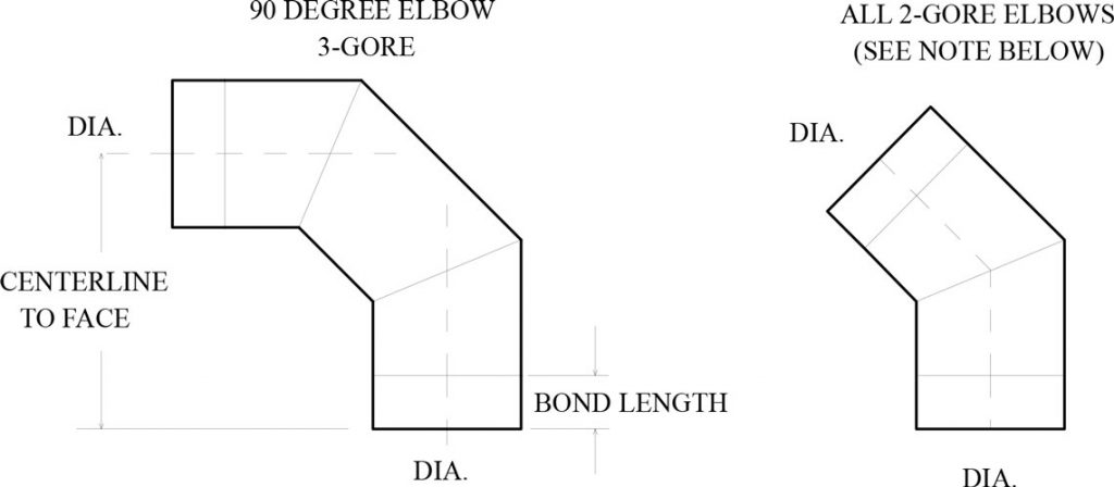
Centerline to face dimensions
90 degree 3-gore elbows
Standard radius = 1-1/2 dia. + bond length
Short radius = diameter + bond length
Note: all 2-gore elbows should be measured at the site by the installers for accurate incorporation into the duct assembly.
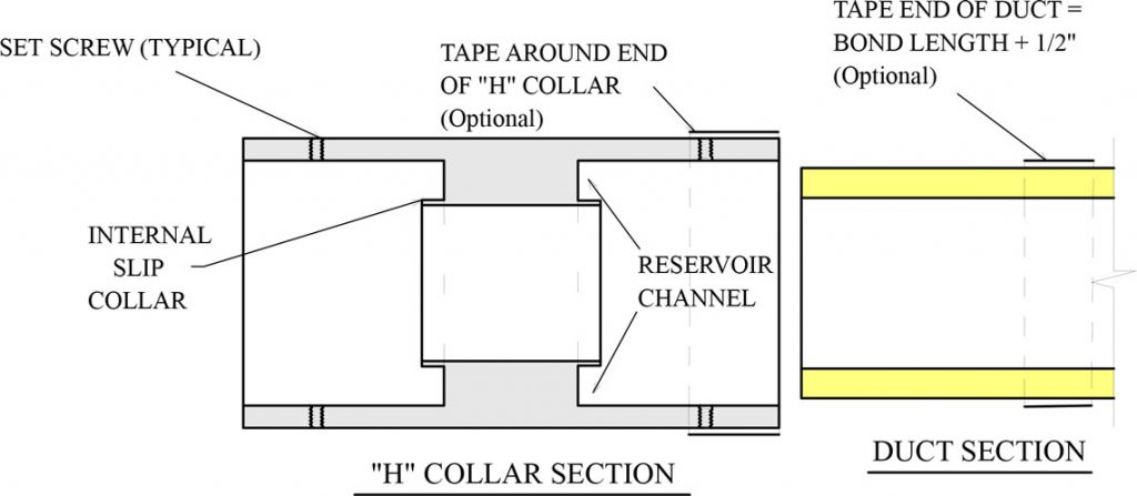
PREPARATION: The H-Collar and duct/fitting surfaces must be clean prior to bonding. Cleaning the exterior surface with an isopropyl alcohol wipe will remove most foreign debris. When the surfaces are ready for bonding, wrap 2” wide tape around the end (optional) of the H-Collar and another strip around the duct a distance of the Bond Length, plus 1⁄2”, back from the end of the duct as shown in the PREPARATION detail below.
PREPARATION
ChemBond Putty Instructions
ATS provides pre-measured individual bonding kits for each H-Collar or U-Collar connection. The kits consist of a container of putty for the given diameter and a second container with the amount of hardener required properly cure the putty mixture. The labels are clearly marked to identify the diameter of duct intended for its use.
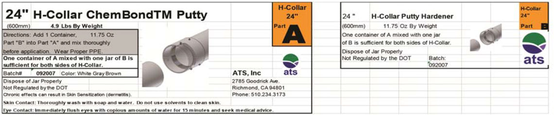
MIXING PUTTY AND HARDENER: Begin by transferring the entire amount of Putty Hardener into ChemBondTM Putty container. Blend the mixture thoroughly for a minimum of 2 minutes, until smooth and even. Blending the mixture thoroughly will yield the required strength and corrosion resistance characteristics of the resin.
| Weight Ratios (Metric) | |
|---|---|
| ChemBond Putty | Hardener |
| Grams | Grams |
| 100 | 15 |
| 200 | 30 |
| 400 | 60 |
| 500 | 75 |
| 1000 | 150 |
| Weight Ratios (Imperial) | |
|---|---|
| ChemBond Putty | Hardener |
| Pounds | Ounces |
| 1 | 2.5 |
| 2 | 5 |
| 3 | 7.5 |
| 4 | 10 |
| 5 | 12.5 |
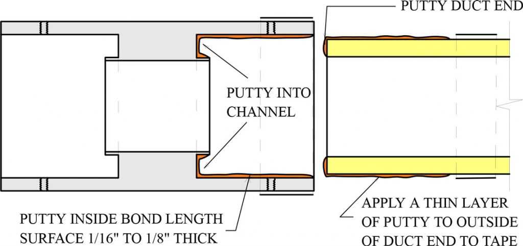
PUTTY MIX APPLICATION (see detail below): Using a tongue depressor or squeegee, apply a liberal layer of Putty Mix to the inside of the H-Collar (approximately 1/16” to 1/8” thick), making sure the Putty Mix is spread into the Reservoir Channel of the H-Collar. Next, apply a thin layer of Putty Mix to the outside surface of the duct/fitting end for the distance of the Bond Length or up to the tape applied to the duct as described in “Preparation” above. Then apply Putty Mix to the end of the duct/fitting.
PUTTY MIX APPLICATION
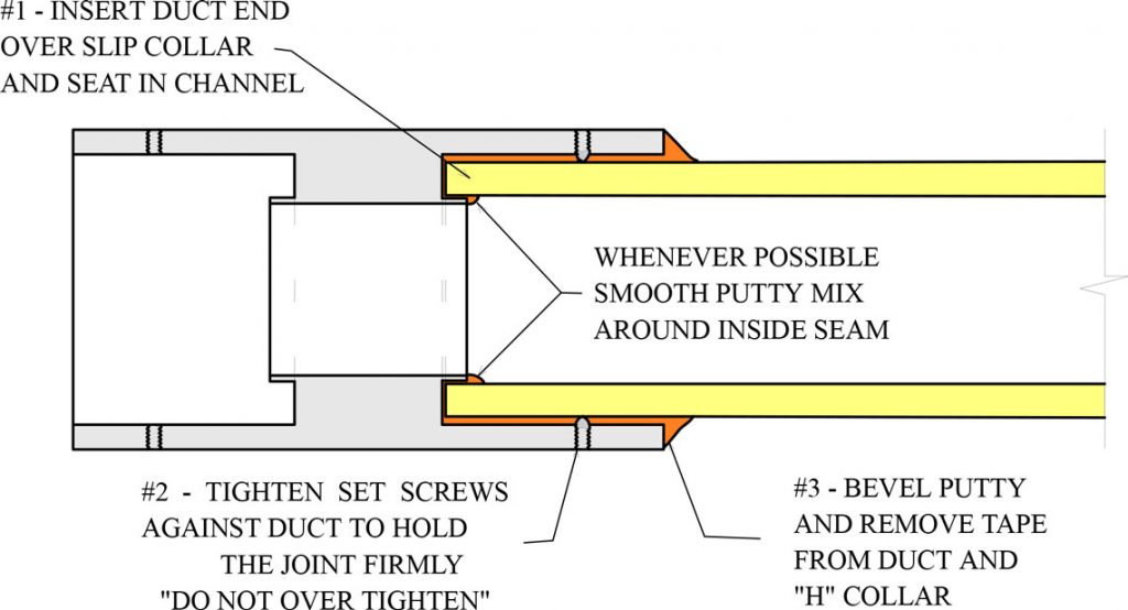
CONNECT AND FINISH (see detail below): Slowly slide the duct/fitting prepared end into the prepared end of the H-Collar, taking care to insert the duct/fitting end evenly into the center of the H-Collar opening. Push the duct/fitting all the way into the H-Collar, until the end slips over the Internal Slip Collar and seats into the Reservoir Channel. Holding the connection firmly, tighten the set screws (see Set Screw Chart next page) until they rest snuggly against the duct/fitting wall, keeping the space around the H-Collar even. DO NOT OVER TIGHTEN THE SET SCREWS; they should hold the duct/fitting end tightly in the H-Collar, so the next connection can be made while the Putty Mix cures, without disturbing the connection.
Smooth the excess Putty Mix on the outside to form a uniform bevel of resin between the H- Collar and the outside duct/fitting surface. Immediately, peel away the tape on the H-Collar and duct/fitting surface, leaving a quality finished joint. NOTE: The ( optional) tape must be removed before the Putty Mix cures. Where possible reach inside the duct and smooth the Putty Mix evenly into the seam of the Internal Slip Collar and duct/fitting connection.
CONNECT & FINISHING JOINT
ATTENTION: For tool connections where the system will be operational immediately, the joints must be cured, prior to system startup. To immediately cure the freshly made joint, wrap an electric drum heater around the center of the H-collar, set the temperature regulator to 180 F (82 C) and apply heat for approximately 5 minutes. Alternatively, a hot air gun can be used to heat the joint and accelerate the cure. Apply heat to the H-Collar and the duct/fitting end. The heat will transfer evenly into the Putty Mix. When the duct/fitting and H-Collar surfaces are hot to touch, remove the heat and the joint will cure in minutes.
DO NOT APPLY HEAT DIRECTLY TO THE PUTTY MIX
SET SCREW CHART
| Diameter Range | Size | Number of Holes | Allen Wrench |
|---|---|---|---|
| 2″ to 10″ | 5/16 NC x 5/16 | 3 | 5/32 |
| 12″ to 24″ | 5/16 NC x 5/16 | 4 | 5/32 |
| *26″ to 34″ | 5/16 NC x 5/16 | 6 | 5/32 |
| *36″ to 46″ | 5/16 NC x 3/8 | 8 | 5/32 |
| *48″ to 96″ | 3/8 NC x 1/2 | 8 | 3/16 |
| *Set screws are not required on sizes > 26ӯ (650 mm) and are available only upon special request. | |||
“U” COLLAR
U-Collars are available on straight duct and fittings (smooth radius or gored elbows, reducers, etc.), as requested by the installer/buyer. Connections are made using the same methods described for the H-Collars, but because the U-Collars are pre-attached to the duct or fitting ends, only one bond connection is required during the bonding process. The U- Collar consists of an internal slip collar, a reservoir channel, setscrews and an external structural collar. There is no structural area to consider when measuring and cutting, however the adjoining duct and fitting ends must fit correctly by sliding over the internal slip collar and into the reservoir channel to ensure a complete seal for ultimate corrosion resistance.
U-COLLAR SECTION
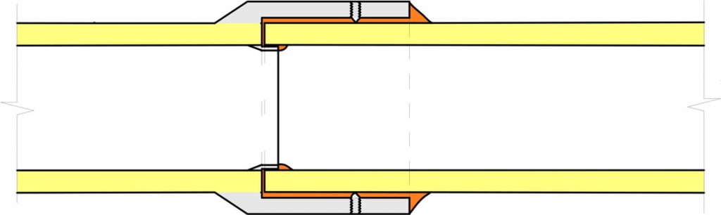
FINISHED JOINT SECTION
FOLLOW H-COLLAR INSTALLATION FOR PREPARATION, PUTTY APPLICATION CONNECTING AND FINISHING THE JOINT