Hot Taps
ATS Saddle Taps on Operating Systems – Hot Taps
Applying ATS Saddle Taps onto Operating Systems
This operation requires a blast gate (or damper) installed in the tap. Be sure to observe the required cleanroom protocol for cleanliness before performing the following procedure. The immediate area of the live tap operation may have to be temporarily closed off with plastic to contain stray particles.
Note: ATS Hot Tap Video is available at atsduct.com for visual instruction.
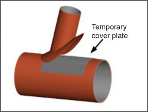
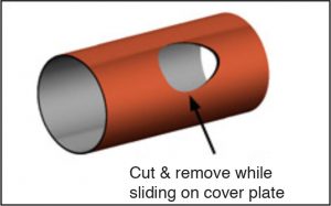
For this operation, two or more workers are recommended. Begin by locating the position of the tap on to the main duct. Place the tap into position. With a china marker or soap stone, mark the main duct along the inside diameter and the outside of the saddle flange. Also, put two hash marks on the tap and the main to mark the centerline for later alignment. This is important, because there will be no other way of positioning the taps in the exact spot once the hole is cut. With a helper vacuuming, drill a 3/8” (10mm) hole on the outside edge of the inside diameter of the tap at the upstream end of the cut-out plate. Drill a 6mm hole near the upstream end of the cut-out plate and insert an eye screw. With the saber saw using a Carborundum or Carbide Tip blade (vacuum operating), place the blade in the 3/8” (10mm) hole and begin cutting around the outside of the inside diameter of the tap. Cut away 3/8” (10mm) extra material around the outside of the inner tap diameter marking until the cut-away plate (to be removed) begins to move easily as the perimeter cut nears completion. At this point slide a sheet metal plate over the cut area close to the eye screw. Hold the eye screw firmly to not allow the plate to fall into the air stream when the cut is complete. A cord can be attached to the eye screw to prevent the plate from falling into the duct.


When the cutting is complete, pull the plate out and away as you slide the sheet metal completely over the hole. Temporarily secure the sheet metal plate to the duct exterior with cleanroom tape. The inside of the cutout plate may have been exposed to hazardous chemicals and must be decontaminated before it is disposed of.
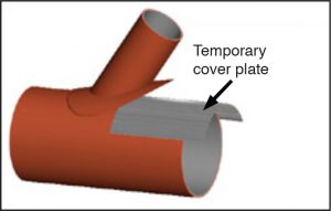
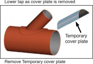
Place 6 mil (6/1000ths inch) clear plastic wrap over tap opening and tape securely. Apply ChemBond™ putty mix to the underside of the saddle tap, spreading the putty evenly–a layer about 1/8” (3mm) thick. Pull away the tape securing the sheet metal cover plate and slide the cover along the centerline of the main duct to the edge of the tap hole. Place the back end of the saddle flange against the main duct and align it with the saddle flange outline previously drawn. As you drop the tap toward the main duct to secure it into position, slide the cover plate out. At the moment the cover plate is removed, force the tap into its set position and hold it firmly until the draw bands are tightened to secure the tap firmly against the main header. (Note that ATS Saddle Taps come standard with draw band guide spacers, which prevent the draw bands from sliding during tightening).
NOTE: As the saddle flange is pressed against the header duct with the draw bands, putty will ooze out around the saddle flange perimeter on the inside and outside of the tap. This excess putty can be used to seal the inside seam and protect the cut edge and exterior surface of the header duct from chemical attack.
Make sure that you have donned appropriate chemically-resistant gloves and gear. Slit the plastic covering the branch opening and insert your gloved hand into the end of the tap, lifting the slide of the blast gate. Reach in and spread the putty that has oozed inside firmly into the seam between the saddle and the cut edge of the header duct. Smooth the putty all around to form a beveled transition along the seam to provide maximum chemical protection. As you pull your gloved hand out of the tap, slide the gate closed to block the introduction of air into the operating system so as not to disturb the air balance. Remove the plastic from the end of the tap. With a squeegee or gloved finger, bevel the excess putty mix on the outside perimeter of the saddle flange to create a smooth seam. Continue with the exterior bond, as previously described (for ATS SaddleTaps 14” and greater).


Please see the page, Taps on Live System, for a test report, summarizing an experiment to show that ATS saddle taps can be applied to main ducts while the system is in operation.
View ATS Hot Tap Installation instructions or watch a video